1.0
Introduction:
Everybody's seen them. Those ominous looking black aircraft, like
something straight out of a science fiction movie. We've all been
told how stealth technology makes aircraft invisible to radar, and
thereby improves the safety and survivability of our military
pilots. Those of us who are technologists have watched the cute
animations showing how radar beams are deflected away from the radar
receiver by skillful use of aircraft geometry, or soaked up by
special radar absorbing materials. What a wonderful job of public
relations! A Madison Avenue advertising agency couldn't have
dreamed up more impressive looking machines, or done a better job of
selling them. This is America's military at its best, winning the
hearts and minds of its citizens, and of course striking fear and
terror in the enemies of democracy, no matter where they are hiding.
Even the American navy (not to be out done by their rivals in the
air force) is building stealth warships.
Too bad its all based on a lie... Yes, stealth technology renders an aircraft (or ship) invisible to conventional radar, when that radar is used in a conventional manner. Yes, during the gulf wars stealth aircraft flew with impunity into Iraq, and evaded 1980s era Russian made radars. All of this is indisputably true. However as I shall elaborate, a multiplicity of stealth countermeasures are both feasible and practical. As you are about to discover, when flying against these countermeasures, stealth aircraft (and ships) are nothing more than very expensive scrap metal. In other words, an extravagant waste of taxpayer money.
1.1.1
Stealth basics:
A quick review of how stealth technology works will prove helpful in
understanding stealth countermeasures. Those readers already
familiar with the techniques embodied in stealth technology may skip
this section. Stealth aircraft and ships are dependent upon three
distinct classes of technology.
Each of these stealth technologies can be circumvented by employing appropriate technologies and/or strategies. I shall address each stealth technology separately (below).
1.2.1
Radar diversion countermeasures:
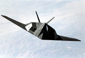
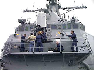
The use of geometry to deflect radar return (bounce) energy away
from the radar receiver represents the corner stone of modern
stealth technology. This technique is employed on such diverse
platforms as the American F117 Nighthawk aircraft (figure 1), and
the DDG (Arleigh Burke class) Aegis guided missile destroyer (figure
2). The technique is based on the fact that only those surfaces
parallel to the electromagnetic wave front will reflect the wave
back to the receiver. In optical terms this is stated as: "The
angle of reflection is equal and opposite to the angle of
incidence". In other words, only a wave front incident at 90
degrees to a surface will be reflected back to the source (radar
transmit/receive antenna). By angling all surfaces with respect to
the probable direction of incoming radar emissions (in most cases,
the horizon), the radar wave is reflected away from the receiver.
Thereby rendering the aircraft or ship invisible to radar.
The scientific paradigm that underlies this technique is known as
ray trace optics, and is based on Pierre Fermat's principle of least
time. From the perspective of ray trace optics, it would seem there
is no method by which this form of stealth technology can be
circumvented. However, there is a more sophisticated optical
paradigm, known as quantum wave mechanics, that allows us to draw a
rather different conclusion...
Those who are familiar with the operational principals of phased array radar systems understand the wave front represented by the "ray" in ray trace optics, is in reality just the in phase portion of multiple superimposed independent waves. This is graphically illustrated in figure 3. 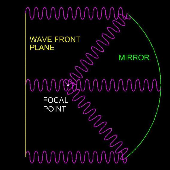
Figure 3
Referring to figure 3, the wave front appears to converge on the focal point because this point is the only location where all in phase waves originating at the incoming wave front plane, are in phase after reflection by the mirror. Phased array radar systems (also known as electronically scanned arrays) make use of this principal by precisely controlling the phase (timing) relationships among a multiplicity of microwave transmitters and receivers. By introducing a progressive set of time delays across the width and/or height of the microwave transmitter array, the in phase plane of the combined array can be rotated through any arbitrary 2D angle, relative to the physical antenna plane. The focal plane of the microwave receiver array can also be adjusted in a similar manner. Under normal operation, the focal planes of both the transmitter array and receiver array are adjusted to the same 2D angle, thereby causing the receiver array to exhibit maximum sensitivity at the 2D angle of the expected target return signal. However, it must be stressed that although the transmitted microwave energy appears to exist only along a single axis (the ray) normal to the in phase plane, that in reality quantum wave mechanics dictates the transmitted microwave energy exists at ALL points surrounding the antenna array. An appreciation of this fact is central to understanding return diversion countermeasures. Consider the situation depicted in figure 4. 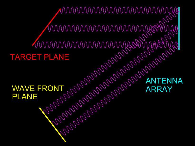
Figure 4
Referring to figure 4, the microwave transmitter array is phased such that the wave front plane (shown in yellow) is off axis from the antenna array. Now consider the target plane (shown in red). Because the transmitted microwave energy exists at all points (not just the in phase plane), AND the target plane angle is complimentary to the wave front plane angle, the resulting reflected wave plane (from the target plane) will be parallel to the antenna array plane. In other words, by pre-distorting the transmitted radar pulse so the wave front plane is complimentary to the target plane, the reflected wave plane will be in phase at the antenna array, and therefore detectable by the radar receiver array. The concept presented in the preceding paragraph represents the basic method of implementing radar return diversion countermeasures. Of course the radar system must have some prior knowledge of the expected range of target angles in order to pre-distort the transmitted microwave pulse. However once a set of actual angles are obtained by painting the target, this represents additional signature information that can be used to identify the type of target. There are two additional advantages to this method.
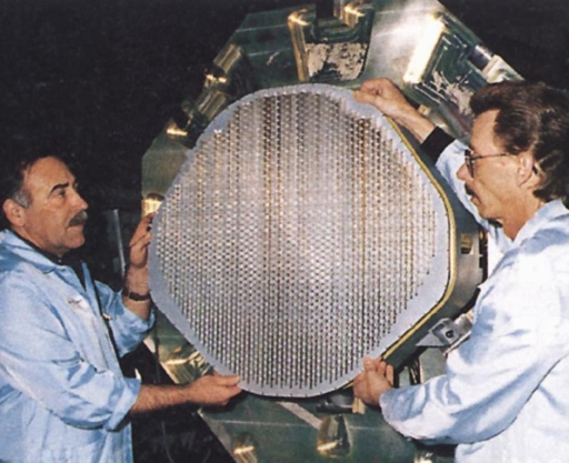
Figure 5 (courtesy USAF)
A word of caution to any nation contemplating the manufacture and/or deployment of stealth aircraft and/or ships. The author has every reason to believe the American F/A 22 Raptor phased array radar (shown in figure 5) is capable of operation in the stealth detection mode as described in this section.
1.2.2
Radar absorption countermeasures:
Radar absorbent materials are based on the principal of converting
coherent electromagnetic energy (radio waves) into incoherent
electromagnetic energy (heat). And when viewed from this
perspective, the term "radar absorbent material" represents a subtle
form of disinformation. The material itself is a liquid composite,
formed from low Q ferrite particles, suspended in a radar
transparent organic binder, applied to surfaces in a manner similar
to conventional paint.
The low Q ferrite particles act as lossy (low efficiency) resonators, thereby transforming incident microwave energy into heat. A wide range of particle sizes are used to allow the material to function across a broad spectrum of frequencies. However, the spectrum of frequencies over which the material will convert microwave energy into heat is not unlimited. In particular, the lower end of the microwave band (200Mhz - 800Mhz) is NOT effectively absorbed. This compromise was considered acceptable, since modern radar systems employ frequencies several octaves higher. Here is the Achilles heel of radar absorbent materials. Lower frequencies require larger ferrite particle sizes, and these in turn require a thicker coating, resulting in surface imperfections (bumps), which impair aerodynamic performance. As a side note, the only F117 ever lost in combat was detected using this very same technique. The wreckage is still on display, available for public viewing at the aviation museum in Belgrade Serbia. Click Here to read Wikipedia article on F117 combat loss (opens in a new browser window). Therefore, the use of low frequency radar, especially when coupled with computer based aperture synthesis to compensate for the lower image resolution is an effective countermeasure to radar absorbent materials.
1.2.3
Infrared signature suppression countermeasures:
Infrared stealth is accomplished by mixing hot exhaust gases with
air at ambient temperature, prior to release into the atmosphere. A
related technique involves spreading the hot exhaust gas plume over
a large area as it's released into the atmosphere. Both methods are
designed to lower the effective temperature of the exhaust plume,
thereby making infrared detection more dificult. However, the
exhaust plume has other characteristics that are detectable, and
when coupled with absence of heat, shout "this is a stealth
platform!"
The detectable signatures of the exhaust gas plume fall into two broad categories.
The physical signatures of the exhaust gas plume result from the large velocity differentials relative to the surrounding atmosphere. This is especially true for jet aircraft. Currently, backscatter Doppler radar in the 500MHz to 1500Mhz region is used to directly measure the motion of the atmosphere in the study of weather related phenomena. Since these systems can accurately measure atmospheric motion in the 10 kilometers per hour range, the measurement of jet exhaust plumes at 100 to 600+ kilometers per hour range will prove very easy to accomplish. As with chemical signature analysis, the use of a coaxial mounted focal plane infrared detector will confirm the stealth nature of the platform. The Chilbolton ACROBAT (Advanced Clear-air Radar for Observing the Boundary layer And Troposphere) is an example of backscatter clear air Doppler radar technology. Click Here for general information on the Chilbolton ACROBAT radar (opens in a new browser window). Click Here for Chilbolton ACROBAT radar system block diagrams (opens in a new browser window). Note: The Chilbolton system actually measures backscatter from moisture suspended in the atmosphere, however since exhaust gas contains large amounts of H2O generated by the combustion process, use of backscatter Doppler radar for stealth platform detection presents no insurmountable problems. A Doppler frequency gate will be able to discriminate between normal atmospheric processes (rain, snow, hail, etc) and the much higher velocities associated with jet exhaust gas plumes. The use of several small (< 4 meter) dishes, under servo control, and fed from a common RF source to maintain phase coherence will result in the same (or better) angular resolution as achieved by the 25 meter dish at the Chilbolton installation.
1.2.4
Miscellaneous countermeasures:
Another method of physical detection is worthy of mention. Although
widely used in WWII, it seems acoustic signature analysis has fallen
out of favor in recent decades. While most stealth aircraft are
very quiet during approach, the authors first hand experience with
an over flight by a B2 bomber indicates this is certainly NOT the
case as the aircraft was departing. This observation may not appear
to be useful, until you consider the situation depicted in figure 6.
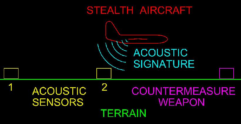
Figure 6
Two acoustic sensors (1 & 2) are sequentially triggered by over flight of the stealth aircraft. Since the distance between acoustic sensors 1 and 2 is known, the time interval between triggers of sensors 1 and 2 yields the velocity of the stealth aircraft. Knowing the aircraft velocity, and the distance between sensor 2 and the countermeasure weapon, allows the weapon to be triggered in advance of stealth aircraft over flight. When employed at a natural choke point such as a long narrow valley, or an artificial choke point such as the mid point between two conventional search radars, the utility of the tactic becomes self evident. A typical countermeasure weapon would consist of multiple mortar launched shells, containing small metal fragments dispersed by a high explosive charge, directly in the flight path of the oncoming stealth aircraft. This countermeasure system has the added advantage of being completely passive, and therefore undetectable by the stealth aircraft. The later generations of stealth aircraft have tried to strike a balance between stealth capabilities and conventional aerodynamic capabilities. This was necessary because the ideal geometry (shape) for maximum stealth is NOT the ideal shape required to achieve maximum aerodynamic performance. Consider the F/A 22 Raptor, America's newest stealth aircraft shown in figure 7 (below) as an example of compromise between stealth performance and aerodynamic performance. 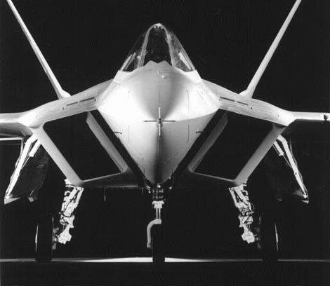
Figure 7 (courtesy USAF)
From this angle, there isn't much area for reflection of a radar beam. Next, look at figures 8 and 9. 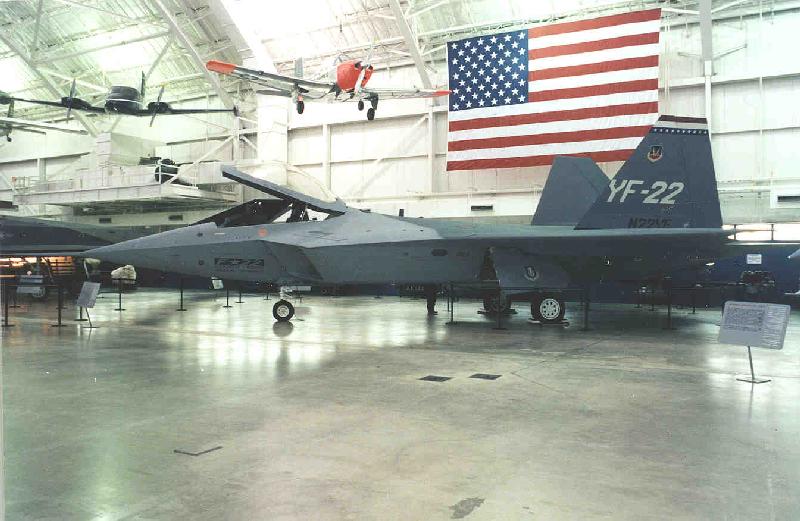
Figure 8 (courtesy USAF)
Figure 9 (courtesy USAF)
Notice how the large flat vertical tail fins (shown in figure 8) and the jet engine air intake side panels (shown in figure 9) make ideal targets for radar diversion countermeasures (as discussed section 1.2.1). Judging from the multiple angled surfaces incorporated into the side panels of the air intake, F/A 22 designers were also concerned about radar reflection from this surface. Obviously this aircraft is optimized for maximum frontal stealth, and side stealth has been sacrificed for aerodynamic performance. Just what one would expect for an air superiority fighter aircraft. However as the F/A designation implies, the F/A 22 Raptor is also intended to function in a ground attack mode. Now suppose a mobile anti-missile battery equipped with a diversion countermeasure style radar (1.2.1 above) is physically separated from a conventional targeting radar located at the installation these systems are defending. Consider the F/A 22 Raptor executing a ground attack mission against this target. As the F/A 22 attacks the defended installation, its onboard systems will detect the conventional targeting radar (located at the installation) and to present the smallest possible radar target, it will keep its nose pointed directly at the conventional targeting radar. However, the anti-missile battery (and stealth countermeasure radar) located some distance away and at right angles to F/A 22 flight path, will have a clear unobstructed view of the vertical tail fins and air intake side panels (figures 8 & 9 above). Furthermore, as discussed in section 1.2.1, electronic countermeasure systems (ECM onboard the F/A 22) won't even detect the anti-aircraft missile battery stealth countermeasure radar. Consequently, the first indication of a trap will be when infrared detectors onboard the F/A 22 inform the pilot of a missile launch. Well, at least the F/A 22 has super cruise (Mach 1.7 without afterburners) so perhaps it will be able to out run the missile, providing the pilot reacts fast enough. Of course this means the F/A 22 will have to break off from its attack of the ground target. And of course the mobile anti-missile battery will be quickly relocated to preclude any follow on attempt to destroy it, preparatory to a second F/A 22 attack on the primary target. A similar situation could be implemented using two aircraft. One acting as bait, and a second aircraft some distance away, equipped with stealth countermeasure radar. This would be especially effective if the second aircraft could use a digital radio link to direct the flight path of a missile launched from the "bait" aircraft. As the scenarios (above) illustrate, even the newest, most advanced stealth aircraft are NOT invulnerable when appropriate technologies and tactics are employed.
1.2.5
Countermeasure deployment:
The effectiveness of stealth countermeasures and tactics discussed
herein can be enhanced by the careful selection of deployment
locations. Since radar and infrared stealth DO NOT mean complete
absence of detectable signature, but only greatly reduced signature.
If follows that stealth platforms will chose penetration and egress
routes that either avoid close approach to traditional detection
systems (search radars, etc.) or use natural terrain features to
reduce the chance of detection. These facts can be used to
advantage in choosing deployment locations for stealth
countermeasure systems. As an example, conventional search radars
are generally deployed with a slight overlap at the limit of the
detection range. This area of overlap, near the limit of detection
range is where a stealth platform will naturally chose for it's
penetration and egress corridor(s), and represents an ideal location
for stealth countermeasure deployment. Long sinuous valleys that
terminate near high value targets and act as natural barriers to
radar would represent another useful penetration and/or egress route
for stealth platforms, and therefore another logical deployment
location for stealth countermeasures.
Stealth naval platforms will employ the hide-in-plain-sight strategy. Since their radar signature will be comparable to that of a small fishing boat, the use of a conventional marine search radar, coupled with advance phased array techniques (1.2.1) will serve to uncover the "shark among the minnows". A conventional search radar would be used to locate targets, each of which would then be examined with the phased array system. Since the (phased array) radar pulse used to paint the target is not in phase, standard ECM suites will fail to detect it, and the stealth platform will not know it's true nature has been exposed.
1.3.1
The politics of stealth:
As defensive weaponry has become ever more accurate and therefore
more lethal, offensive delivery platforms (ships, aircraft,
missiles, etc) have become increasingly dependent upon on various
forms of stealth to achieve mission objectives. This trend of
deploying stealthy offensive weapons platforms has disturbing
political consiquences. Political restraint is largely based on the
perceived risk/reward ratio of military action. And stealth
technology has the effect of lowering the perceived political risk
of belligerent behavior. Therefore a government in possession of
stealth weapons platforms is far more likely to embark upon a course
of aggression. When viewed from this perspective, it becomes
apparent that stealth technology represents a shift away from
traditional military defense, to a more offensive military posture.
As a consequence, the widely held belief that stealth technology
enhances pilot safety and mission survivability is false. Since any
added margin of safety provided by stealth technology is more than
offset by the tendency of political leaders and military planners to
employ stealth aircraft on missions and in environments that would
be considered suicidal for any conventional aircraft. Even a
cursory examination of America's deployment and use of stealth
technology lends ample credence to these conclusions.
Furthermore, as I have so amply demonstrated herein, stealth technology represents a false promise of invulnerability. Therefore governmental appropriations for additional development and/or deployment of stealth weapons platforms is both wasteful of taxpayer money, and ultimately counterproductive to the goal of national security. Some commercial (aerospace) corporations and governmental agencies will no doubt try to accuse me of revealing classified (secret) information. However, when the Serbian military were capable of successfully attacking and destroying an F117 stealth fighter in March of 1999, it becomes blatantly obvious it is NOT the effect my disclosures will have on the military balance of power that worries these corporations and governmental agencies. To the contrary, it is the damage my disclosure will do to their carefully choreographed PR campaign that motivates their cries of outrage. A PR campaign aimed not at Belgrade, Moscow or Beijing. Rather a PR campaign aimed squarely at you, the American voter and tax payer. Make no mistake, military planners in Moscow and Beijing are fully aware of stealth technology limitations and flaws. This is why there has been no great rush by these nations to emulate America's growing dependency on stealth technology. Contrary to popular myth, America didn't win the cold war with superior military technology. America buried the Soviet Union with video games, fax machines, and Chevrolets. It was economic collapse that doomed the communists, not military defeat. And sadly, as America squanders untold billions of dollars on weapons that will never live up to their promise, and further billions on wars it has no chance of winning, it becomes increasingly apparent that economic collapse will be the ultimate demise of America as well...
1.3.2
Summary:
As I have shown, stealth platforms are far from invulnerable when
the appropriate countermeasure technology and tactics are employed
(1.2.1, 1.2.2, 1.2.3 & 1.2.4). Many of these countermeasure
techniques are inexpensive, and stealthy in and of them selves
(1.2.1, 1.2.4). Furthermore the mere possession of such
countermeasure technology will, if known to the aggressor, serve as
a deterrent against potential future aggression. In part 2, we
shall examine some practical engineering examples.
1.3.3
Disclaimer:
ALL information contained herein is derived from public sources,
widely accepted scientific principles, and/or authors first hand
experience. The author has NO written or verbal agreement with ANY
governmental agency forbidding disclosure of the information
contained herein. In disclosing this information, the author is
exercising his right to free speech as a private citizen of the
United States of America.
End.
Stealth Countermeasures
|